This Article was written and provided by community member Dan W.
ROG Ally, Meet Sakura Retro Modding
Earning My Modern Gaming Side Quest
Like any good member of the RH community, I spend a large portion of my gaming time playing retro games, specifically the RH Games of the Month. Every now and again however, I come across a modern title which piques my interest enough to earn my focus. I like to view these as my Gaming Side Quests. If GOTM is the ongoing story, then I view these modern games as my sidequests.
My current sidequest is Starfield, and it’s only the second modern game that I’ve invested significant time in this year, after Tears of The Kingdom.
I recently got my hands on a ROG Ally through a trade, mainly as I wanted a travel companion on which I could play Starfield during long train or plane rides that I had ahead of me – for the second year running. I was due to spend more of November living out of a hotel than I was at home. To my surprise, within a few days I realized that this was more than just a Starfield device, and that due to the ergonomics, screen, controls and overall “feel” of the Ally, that this was now my “one and done” device, the device which would hope for the theoretical award as handheld I’d rescue from a fire, if I could only save one.
Yet earning a coveted title such as that doesn’t mean a handheld is immune from tinkering. Last month I wrote about putting Batocera on the Steam Deck, mentioning that, to me at least, adding small customizations to a handheld is part of my process to make each device “mine”.
Visually, one of my favorite customizations is the pad and button replacement I completed on my original Miyoo Mini, replacing the original grey pad and menu buttons with those taken from a broken black MM, and with the face buttons being replaced with some from Sakura Retro Mod, resulting in – what is to me – a striking black-on-white contrast. So, when Sakura Retro Mod announced some ROG Ally Buttons, these seemed like an ideal place to start my new handheld’s journey to customization, especially since the Ally’s original buttons are the least visually pleasing aspect of the device – at least to me. Some Starfield themed stickers were also available, so I grabbed them too.

I was part of the ROG Ally button pre-order, and when they arrived, I noticed that the installation instructions weren’t yet available. Showing my overconfidence, I decided to install them without instructions, documenting my steps as I went along. Turns out installing buttons in the ROG Ally is much more advanced than any button swap I’ve done to date and requires pretty much every component to be removed from the Ally’s shell including the motherboard and both daughter boards.
This article is designed to be a guide to help anyone else through this journey.
To make the whole process as easy to follow as possible. I’ve broken the disassembly and reassembly down into steps, with each step consisting of instruction text, and an image (which I’m labeling fig 1, fig 2 etc.) Whenever removal of a screw, cable or connector is required, I’m highlighting each one in some combination of Orange, Purple, and Green.
Disassembly
Ingredients
The patient is a ROG Ally which has been previously opened in order to upgrade the SSD to 2TB, following the Phawx’s instructions.
Donor parts (buttons and stickers) were ordered from Sakura Retro Modding on Etsy.
Assistance was given by my set of screwdrivers (all that was needed turned out to be a small Phillips screwdriver), an unopened pack of playing cards (to put under the Ally, so that the weight of the Ally wasn’t put on the analog sticks during disassembly), and some wipes (to ensure the front of the Ally is clean).

Step 1 – Removing The Back Cover
There are 6 screws in the back cover of the Ally. In order to remove the back cover, 5 of these screws need to be removed (these are circled in orange in figure 1), and the 6th loosened (circled in purple in figure 1).
The back of the ROG Ally can be pried open more easily than most handhelds. I recommend using nothing more than a fingernail, starting at the top edge, next to a shoulder button and then running the fingernail along the top, between the two halves of the case, then continuing along the rest of the seam. A guitar pick can be used and an alternative to fingernail if needed.
There are no components attached to the back cover, and the cover should come off easily, with no complications, revealing the innards.
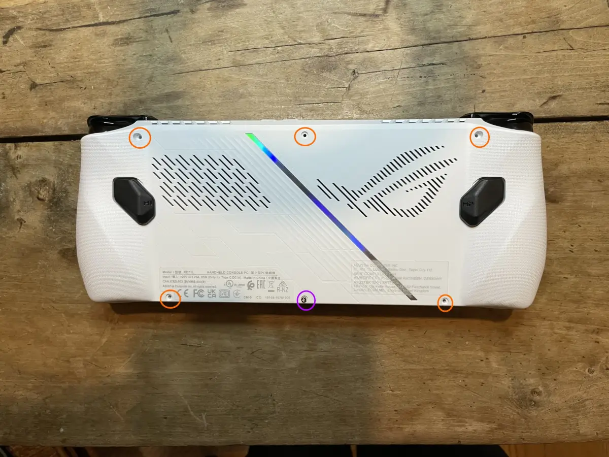
Fig 1
Step 2 – Removing The Battery
I was taught when taking apart computers, that the first thing to do is disconnect the power. This can be completed by gently pulling the power cable out of the connector (highlighted on figure 2 in purple).
After the is power disconnected, there are four screws holding the battery in place which need to be removed (highlighted in orange on figure 2)
The ribbon cable which connects the two analogue stick daughter boards together is stuck to the Ally’s battery. To allow it to come out with the battery, this needs to be unclipped at each end. Open the plastic clips (highlighted in green on figure two) gently by putting a fingernail or prying tool, and free the ribbon cable. If this is your first time removing a ribbon cable, I would suggest looking up a few videos on how to safely open and close ribbon cable clips, as if the clips get damaged, the whole board will need replacing.
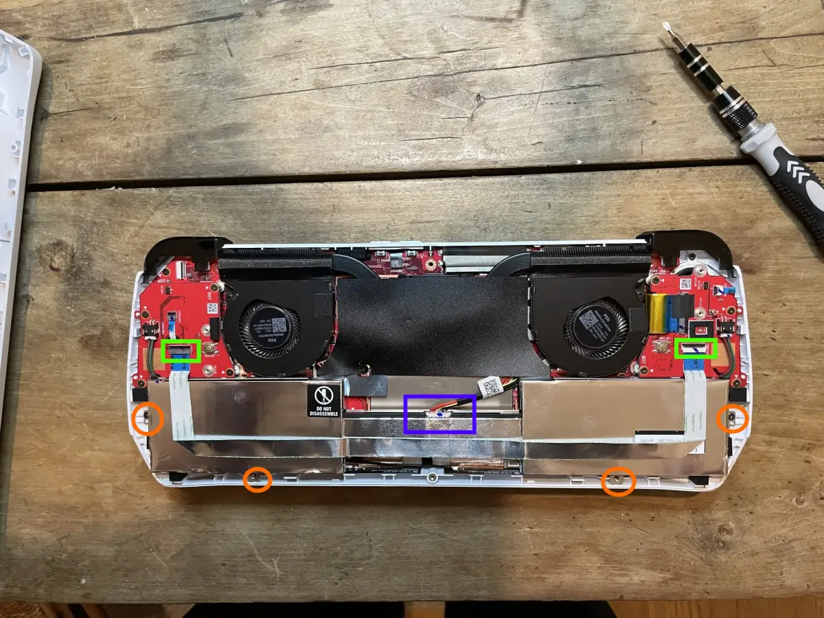
Fig 2
Step 3 – Removing The Left Side Daughter Board
The left-hand side (as you look at it) daughter board is the easier of the two to remove.
There is a tiny ribbon cable (highlighted in purple on figure 4) to unclip and 4 screws (highlighted in orange on figure 4) to remove, after which the daughter board can be taken out.
The larger cable to the bottom left of the board does not need to be disconnected during removal. I found the most challenging part of this step to be feeding the ribbon cable through the hole in the board, since the plastic kept catching. Like every part of this disassembly, it’s worth prioritizing carefulness over speed.
If the black joystick remains in the case, when you remove the daughter board, gently push it through from the other side and keep with the removed board.
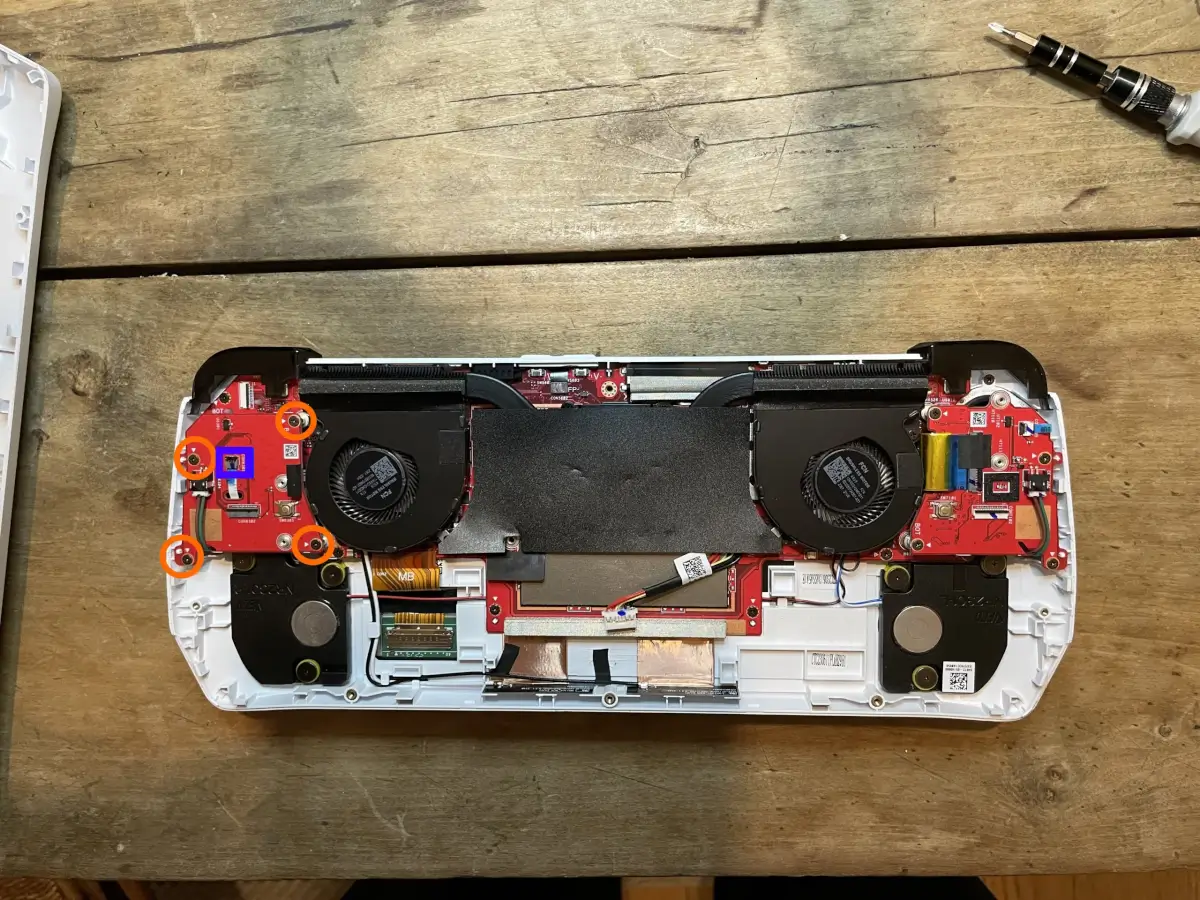
Fig 3
Step 4 – Removing The Right Side Daughter Board
As with the daughter board from the other side, a tiny ribbon cable (highlighted in purple on figure 4) and 4 screws (highlighted in orange on figure 4) need to be removed. The ribbon cable for the board doesn’t need to be fed through a hole so will be easier to deal with.
In addition to what was required for the previous daughter board, there is another ribbon cable (highlighted in green on figure 4). This ribbon cable is held down with tape, which will need to be removed.
Once the four screws and the two ribbon cables have been removed, the daughter board can come out.
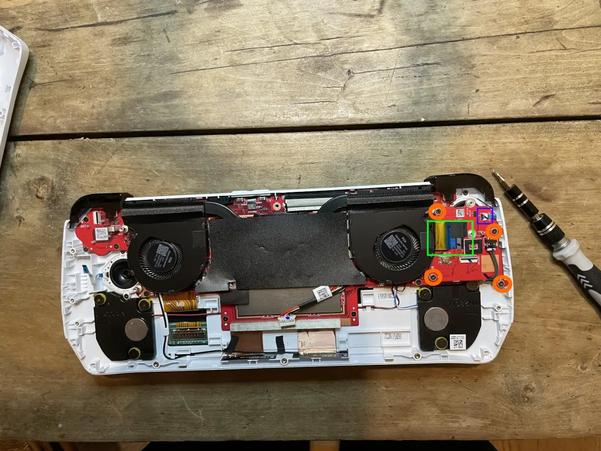
Fig 4
Step 5 – Removing The Screws From The Motherboard (And a Connector)
All that’s left is to remove the motherboard. This is also the point where things get more complicated.
First step towards removing the motherboard is to remove all the screws holding the motherboard in place. There are 2 large screws by the fans and 7 smaller screws around the circumference of the motherboard (all screws are highlighted in orange in figure 5.)
There is also a tiny catch (highlighted in purple in figure 5) which needs to be unclipped, this can be done with a fingernail and while care should be taken, this isn’t as fragile as the ribbon cables.
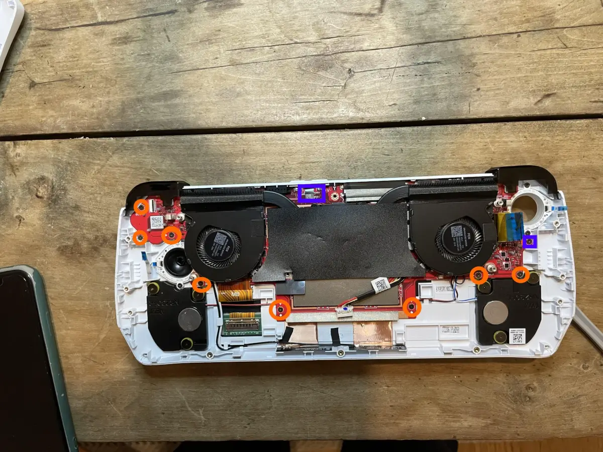
Fig 5
Step 6 – Lifting Up The Left Fan
Inconveniently, there are some connectors under the left fan which need to be disconnected before the mother board can be removed. Since the screws have been removed in the previous step, all that’s holding the fan in place is some tape at the top of the fan.
The fan, tape and all, can be gently pulled away from the cooling pipe that it is attached to. Personally, I saved the tape for reinstallation, but there is throwing it away and replacing it with fresh tape.
Step 7 – Disconnecting The 3 Motherboard Cables
Now that the fan is disconnected, the cables are accessible, and the three connectors preventing motherboard removal will need to be addressed.
Connector 1 is the Wi-Fi antenna. There are two cables, white and black (highlighted in orange in figure 6). The cables will be taped to the motherboard and that tape will need to be removed too.
Connector 2 is a ribbon cable to the front of the shell, and this might be for the touchscreen. This is located slightly below the tape that was holding the wifi cables in place (highlighted in purple in figure 6), Removing this requires the same care used from previous ribbon cables.
The final connector is a sound cable hidden under the right-side fan (the approximate location is highlighted in green in figure 6.) When the right-side fan is lifted up, which can be done without removing the right fan, the cable is obvious, and can be removed with gentle pulling.
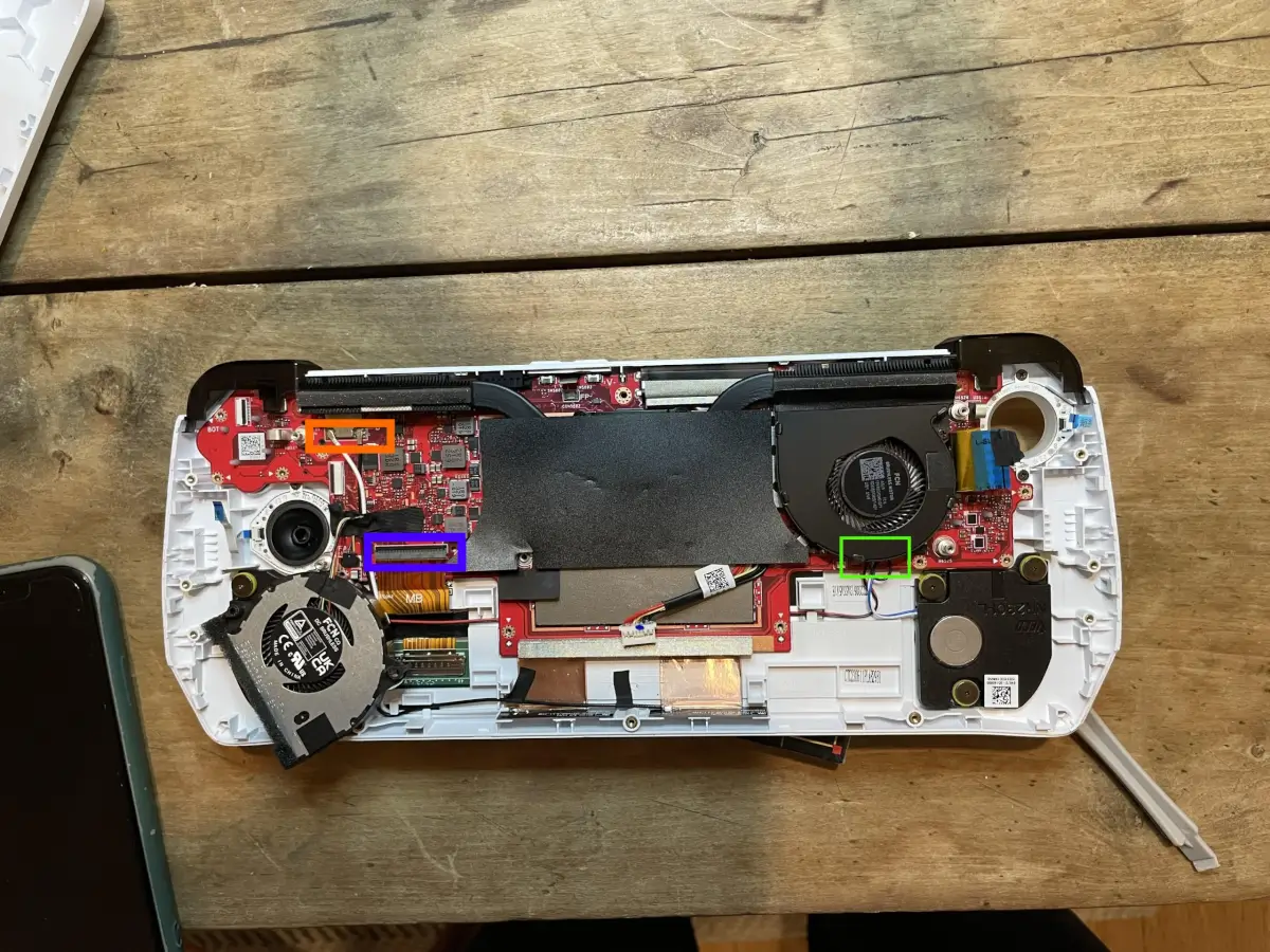
Fig 6
Step 8 – Removing The Motherboard
Finally, everything else is disconnected and the motherboard can be removed. I found that the easiest way to remove the motherboard was to grab it with my index fingers near the bottom and “jiggle” it loose. It should not require much pressure. If there is any resistance, it is likely that a rogue screw or cable remains in place, so it’s worth being aware and double checking everything from steps 5-7 was removed, if there’s any difficulty moving the board.
The motherboard should come off as one whole, with the cooling and SSD still in place.
Step 9 – Removing The Stock Buttons And Putting In The New Ones
Nothing is holding the old buttons in place, and they should come out easily pressed from the other side (as in, pressing from the front of the Ally).
The new buttons can be put in place, and there are bits of small guidance plastic on the sides to ensure that the buttons fit in the right way up – although the guidance plastic are subtle and nowhere near as obvious as those in devices like the Retroid Pocket 3+.
When the buttons are in place, I think it’s worth taking the time to turn the ally around, holding the buttons in place with your fingers, to make sure the letters/symbols are around the right way.


Reassembly
That’s it.
No more teardown, and the buttons are in place. All that’s needed now is to put the Ally back together again.
Step 10 – Putting The Motherboard Back In Place
The motherboard should be able to gently be aligned back to where it was. The key word during this step is gentle, and no direct pressure that bends the board should be applied. All the loose cables need to be kept clear as the motherboard is put back.
After the motherboard is aligned, the L1 and R1 buttons need to be checked to make sure they feel like they bid before. If they don’t, the reassembly need to be paused, the motherboard removed and reseated, until the L1 and R1 buttons feel as expected when clicked.
When all is good with the shoulder buttons, the nine screws that held the motherboard in place need to be put back – these are the ones in orange in fig 5.
The decision to put the screws back in place before the cables was made, so that the action on the new face buttons can be tested as soon as possible. So that any issues can be addressed. Once the screws are in place, the Ally can be turned over, and the buttons pressed. If it feels like there’s any issue fully depressing them, it’s worth unscrewing the screws, and checking if any dirt or other particles have made their way between the buttons and the contacts. If some of the buttons feel more stiff than the others, it’s worth checking all the screws are tightened.
I can not emphasize this enough, the screws should never be forced to tightening, it’s possible to damage the motherboard.
Step 11 – Reconnecting The Cables And The Left Fan
The four sets of cables need to be reconnected to their respective connections after the motherboard is put in place, but before the left fan is put back.
The four connectors are:
The tiny connection at the top of the board shown in the purple square in fig 5.
The speaker connector shown in the green square in fig 6.
The main connector shown in the purple square in fig 6.
The two Wi-Fi antenna cables shown in the orange square in fig 6. White goes on the left and black on the right. Best process is to secure these cables (and the fan cable) with tape like they were at the start, but I have to say I just left them untaped.
The next step is to put the left speaker back in place. When I did this, there was enough stick left on the tape originally in place for it to be reused, but there’s no issue using an alternative.
Step 12 – Reconnecting The Daughter Boards
Putting these back in is so much easier than taking them out. There are 3 ribbon cables (2 on the right, and one on the left) and 8 screws (4 on each) to connect. The trickiest part to me was making sure the tiny ribbon cable on the left came through the hole on the daughter board without it catching.
The screws and connectors are highlighted in fig 3 and 4.
Step 13 – Reconnecting The Battery
As with everything else, reconnecting the battery falls into three actions. 1) Gently putting the part in its place, ensuring none of the cables are caught. 2) Replacing the screws. 3) Reconnecting the cables. As with everything the corresponding illustration – in this case fig 2, can be used as a good reminder.
If I had one piece of advice for anyone wanting to follow these instructions, it would be this: don’t do as I did, and damage the catch on the left side daughter board, causing £30 worth of damage.
Step 14 – Putting The Rear Case Back On
The final step is to put the rear case back on, clicking it in place, and then putting the 6 screws back (remember the center bottom screw can’t be removed from the case.)
Step 15 – Connect The Power Adapter, Power On And Check Everything Works
The ROG Ally has been set up with an odd quirk, meaning if it has been opened, it won’t power on unless the power cable is connected. After the first power on, it returns to usual and can be powered on and off as usual, with or without the cable.
Once the cable is connected, and the Ally is powered on, this is the time to check that everything -specifically the controls – are working properly. If there’s an issue, the Ally will need to be opened up again and every step will need to be checked for mistakes.
Step 16 – Applying The Stickers To The Front
Compared to the taking the Ally apart to replace the buttons, applying the front stickers is an easy task.
The most important part of application is to make sure the front of the Ally is clean before the stickers are applied. My preferred method is to use the Wet and Dry wipes that come with most retro handhelds and screen protectors, followed by a proper wipe down with a microfiber cloth, in order to make sure the front of the device is clean, dry, and free from dust.

Once the front is clean, the stickers can be peeled off and applied. These Sakura Retro Mod stickers tend to be a lot easier to apply than those from the likes of dBrand, which often require the use of a hair dryer during application.
For the Sakura Retro Mod stickers, my advice to any application is to use the holes for the sticks/pads/buttons as the guide for lining up the stickers, and (as far as is possible), applying the sticker in a single fluid motion. If a mistake is made, the sticker should be immediately removed and reapplied as quickly as possible. After application, any roughness around the edges can be reduced by going round and around with a microfiber cloth.

And that’s it: Completion.

Can It Play My Modern Gaming Side Quest?
Asus released an updated graphics driver for the ROG Ally at the end of August which specifically addressed Starfield performance. It’s version 31.0.21029.6002, and it should be available in the MyAsus app.
Once that update is installed, Starfield runs remarkably well for a handheld device. My personal preference is to set all the in-game graphical settings to low, and set the Ally’s resolution to 720p within the armory crate. I can’t guarantee a framerate over 30fps, but coming from playing the Xbox Series and xCloud versions of Starfield, this is the experience I’m used to. I play on performance mode, and I’ve only had one crash – and this was in a busy city seen on Jemson.

The intro music sounds *chef’s kiss* on the Ally’s front facing speakers.


720p might not be perfection, but it doesn’t half look bad on the Ally’s screen.
And can it play Game of The Month
Each month, 3 games are selected in the RH Discord as the server’s “Game of The Month” – each game is from a different timeframe. One will originally have been released prior to NYE 1995, one released between 1996-1999 and one released in 2000 or later. For February, the theme chosen in the discord is “Follow-Up February”, where the community picks games which are follow ups to previously chosen games. After voting, we were left with Kirby’s Dream Land 2 on the Game Boy, Metal Slug 2 on Neo Geo and Metroid Prime on the GameCube
As it is effectively the most powerful widely available handheld, the Rog Ally (with or without improved buttons) can play any of this month’s games.
Metroid Prime has been on my backlog for the longest time – indeed it was my nomination for this month’s GOTM – and as an owner of a physical copy of the Switch Remaster I began to complete the game on my Switch OLED (on the whole, remakes and remasters – but not remixes – are consider valid ways to play through GOTM games). While it doesn’t touch the very top tier of games I’ve discovered as part of GOTM – those are Klonoa and Parasite Eve – it comes close. Playing Metroid Prime in 2024 makes the game feel like it’s hardly aged (even emulating the GameCube release), and walking through the remnants of a fallen civilization, slowly uncovering their story makes it easily my favorite GOTM experience in the last 12 months.
Making sure my Ally doesn’t feel left out, I make sure it can run the original version, using Retroarch. I’m sure the standalone version of Dolphin has better performance but never mind that. I played through the opening space station level. One thing which really strikes me is how much better the audio is on the opening cut scene using the Ally, even if the graphics and especially the colors, lag behind the remaster.
Finishing Metroid Prime, or (either of the other two games) within February (and posting proof to the discord) will gain me a point that I can eventually exchange for RH Merch.
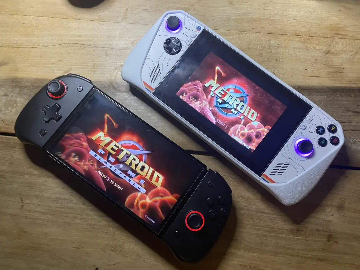
The original and the Remaster’s in-game title screen
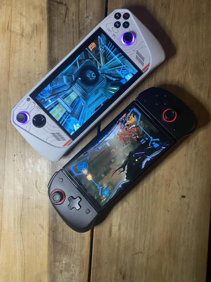
While upscaled GC on the Ally looks great, it still doesn’t compare to the Remastered on the Switch OLED
Further Reading
The Sakura Retro Mod custom buttons and stickers are available on Etsy and can be found here: https://www.etsy.com/uk/shop/SakuraRetroModding?section_id=44489409
I have a lot of love for iFixit, and their guides for upgrading various devices. Before opening my ROG Ally, I watched their teardown video multiple times, it can be found here:
https://youtu.be/IxPgBhm6tHs?si=pBngQ0Y2LloxFm9I
The graphics driver needed to play Starfield on the ROG Ally should be downloadable from the MyAsus app. If for any reason it can’t be, it can be downloaded here: https://dlcdnets.asus.com/pub/ASUS/IOTHMD/Image/Driver/Graphics/35393/AMD_Graphic_DriverOnly_ROG_AMD_Z_V31.0.21029.6002_35393.exe?model=ROG%20Ally%20(2023)
This wasn’t the first time I opened my ROG Ally, as soon as I got it, I immediately upgraded the SSD to a 2TB drive, following the instructions from The Phawk’s video.
https://youtu.be/0amz40sIud8?si=–fV9JtcQpmXSN2W
If other hardware mods for the ROG Ally are of interest, 3rd part hall effect joysticks are available for purchase, and will be my next project. They can be bought here: https://www.handhelddiy.com/products/hall-joystick-for-rog-ally-1
If the worst happens and a ROG Ally is damaged during tear-down, replacement parts can be bought from the Asus Store
The European store can be found here: https://en.accessoires-asus.com/ally-console/
The American store can be found here: https://www.a-accessories.com/rog-ally-nr2301l-92121-85093.htm
What did you think of this article? Let us know in the comments below, and chat with us in our Discord!
This page may contain affiliate links, by purchasing something through a link, Retro Handhelds may earn a small commission on the sale at no additional cost to you.
